DOOR LOCK SWITCH SHORT TO GROUND
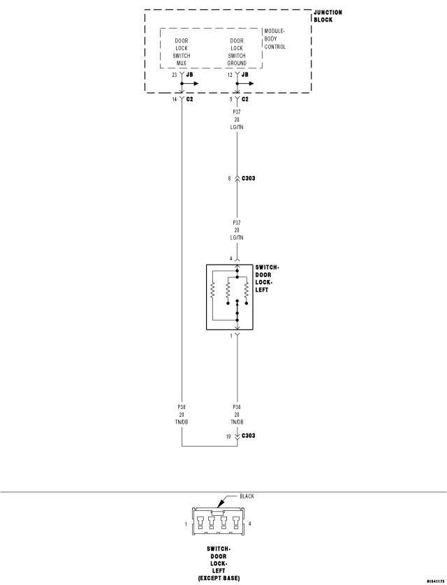
For a complete wiring diagram Refer to Section 8W.
- When Monitored:
Whenever the ignition is on.
- Set Condition:
When the BCM detects a voltage of less than 0.25 volts on the door lock switch mux input for over 5 seconds, this code will set. The normal voltage on the circuit is between 0.25 and 4.75 volts depending on switch positions. NOTE: Left and right switches are in parallel.
| Possible Causes |
| (P36) LEFT DOOR LOCK SWITCH MUX WIRE SHORT TO GROUND |
| (P36) RIGHT DOOR LOCK SWITCH MUX WIRE SHORT TO GROUND |
| LEFT DOOR LOCK SWITCH - SHORTED |
| RIGHT DOOR LOCK SWITCH - SHORTED |
| JUNCTION BLOCK SHORT TO GROUND |
| BODY CONTROL MODULE - DOOR LOCK SWITCH MUX SHORT TO GROUND |
Diagnostic Test
1.CHECK TROUBLE CODEDoes the scan tool display DOOR LOCK SWITCH SHORT TO GROUND?
Yes
- Go To2
No
- Problem is intermittent and not present at this time. Using the wiring diagram/schematic as a guide, inspect the wiring and connectors and repair as necessary.
- Perform BODY VERIFICATION TEST - VER 1. (Refer to 8 - ELECTRICAL/ELECTRONIC CONTROL MODULES - STANDARD PROCEDURE)
2.CHECK THE LEFT DOOR LOCK SWITCH MUX CIRCUIT FOR A SHORT TO GROUND
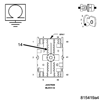
Is the resistance below 1000.0 ohms?
Yes
- Go To3
No
- Go To4
3.CHECK LEFT DOOR LOCK SWITCH MUX WIRE FOR A SHORT TO GROUND
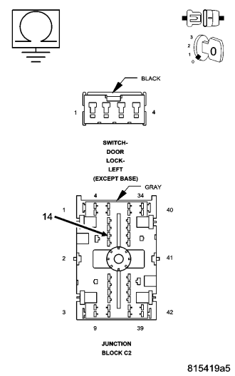
Is the resistance below 1000.0?
Yes
- Repair the (P36) Door Lock Switch Mux wire for a short to ground.
- Perform BODY VERIFICATION TEST - VER 1. (Refer to 8 - ELECTRICAL/ELECTRONIC CONTROL MODULES - STANDARD PROCEDURE)
No
- Replace the Left Door Lock Switch.
- Perform BODY VERIFICATION TEST - VER 1. (Refer to 8 - ELECTRICAL/ELECTRONIC CONTROL MODULES - STANDARD PROCEDURE)
4.CHECK THE RIGHT DOOR LOCK SWITCH MUX CIRCUIT FOR A SHORT TO GROUND
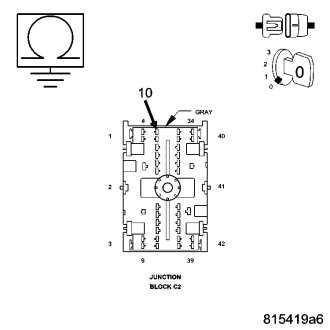
Is the resistance below 1000.0 ohms?
No
- Go To6
Yes
- Go To5
5.CHECK RIGHT DOOR LOCK SWITCH MUX WIRE FOR A SHORT TO GROUND
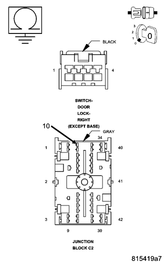
Is the resistance below 1000.0 ohms?
Yes
- Repair the (P36) Door Lock Switch Mux wire for a short to ground.
- Perform BODY VERIFICATION TEST - VER 1. (Refer to 8 - ELECTRICAL/ELECTRONIC CONTROL MODULES - STANDARD PROCEDURE)
No
- Replace the Right Door Lock Switch.
- Perform BODY VERIFICATION TEST - VER 1. (Refer to 8 - ELECTRICAL/ELECTRONIC CONTROL MODULES - STANDARD PROCEDURE)
6.CHECK THE JUNCTION BLOCK FOR A SHORT TO GROUND
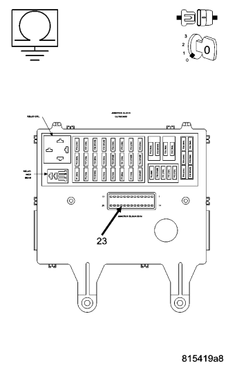
NOTE: Ensure the Junction Block C1, C2 and C3 connectors are connected before proceeding.
Is the resistance below 2000.0 ohms?
Yes
- Replace the Junction Block in accordance with service information.
- Perform BODY VERIFICATION TEST - VER 1. (Refer to 8 - ELECTRICAL/ELECTRONIC CONTROL MODULES - STANDARD PROCEDURE)
No
- Replace the Body Control Module in accordance with service information.
- Perform BODY VERIFICATION TEST - VER 1. (Refer to 8 - ELECTRICAL/ELECTRONIC CONTROL MODULES - STANDARD PROCEDURE)