PINION DEPTH-BEARING PRELOAD-GEAR BACKLASH
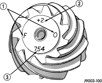
Ring and pinion gears are supplied as matched sets. Gear match numbers (3) for the ring and pinion gear are etched onto each gear. A plus (+) number, minus (–) number or zero (0) is etched into the face of the pinion gear (2). This number is the amount (in thousandths of an inch) the depth varies from the standard depth setting of a pinion etched with a (0).
Compensation for pinion depth variance is achieved with a select shim. The shims are placed between the rear pinion bearing and the pinion gear head.
If installing a new gear, note the depth variance number of the original and replacement pinion. Add or subtract this number from the original depth shim to compensate for the difference in the depth variances. The numbers represent thousands of an inch deviation from the standard. If the number is negative, add that value to the required thickness of the depth shims. If the number is positive, subtract that value from the thickness of the depth shim.
Pinion Gear Depth Variance Chart: Note where Old and New Pinion Marking columns intersect. Intersecting figure represents plus or minus the amount needed.
| Original Pinion Gear Depth Variance | Replacement Pinion Gear Depth Variance | ||||||||||
| −4 | −3 | −2 | −1 | 0 | +1 | +2 | +3 | +4 | |||
| +4 | +0.008 | +0.007 | +0.006 | +0.005 | +0.004 | +0.003 | +0.002 | +0.001 | 0 | ||
| +3 | +0.007 | +0.006 | +0.005 | +0.004 | +0.003 | +0.002 | +0.001 | 0 | −0.001 | ||
| +2 | +0.006 | +0.005 | +0.004 | +0.003 | +0.002 | +0.001 | 0 | −0.001 | −0.002 | ||
| +1 | +0.005 | +0.004 | +0.003 | +0.002 | +0.001 | 0 | −0.001 | −0.002 | −0.003 | ||
| 0 | +0.004 | +0.003 | +0.002 | +0.001 | 0 | −0.001 | −0.002 | −0.003 | −0.004 | ||
| −1 | +0.003 | +0.002 | +0.001 | 0 | −0.001 | −0.002 | −0.003 | −0.004 | −0.005 | ||
| −2 | +0.002 | +0.001 | 0 | −0.001 | −0.002 | −0.003 | −0.004 | −0.005 | −0.006 | ||
| −3 | +0.001 | 0 | −0.001 | −0.002 | −0.003 | −0.004 | −0.005 | −0.006 | −0.007 | ||
| −4 | 0 | −0.001 | −0.002 | −0.003 | −0.004 | −0.005 | −0.006 | −0.007 | −0.008 | ||
PINION DEPTH MEASUREMENT
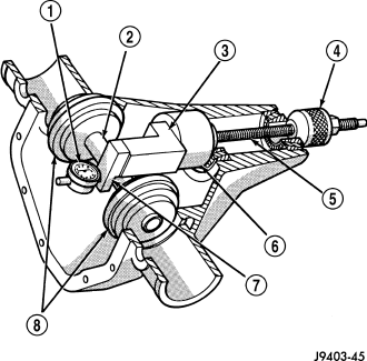
Measurements are taken with pinion bearing cups and pinion bearings installed in the housing. Take measurements with Pinion Gauge Set and Dial Indicator C-3339 (1).
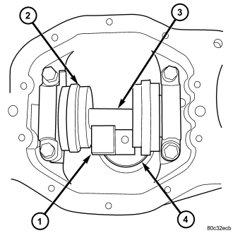
NOTE: Arbor Discs 6732 has different step diameters to fit other axles. Choose proper step for axle being serviced.
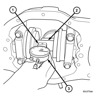
DIFFERENTIAL SIDE BEARING PRELOAD AND GEAR BACKLASH
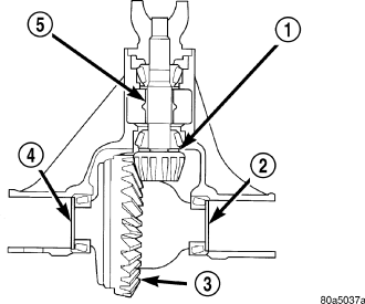
Differential bearing preload and gear backlash is achieved with selective shims (2) (4) located between the differential bearing cups and differential housing. Shim thickness is determined using Dummy Bearings D-348 and Dummy Shims 8107 in place of the differential side bearings and preload shims.
Before measuring differential bearing preload and gear backlash, pinion gear depth must be established and pinion gear prepared installation. Pinion gear depth is essential to establishing gear backlash and tooth contact patterns.
PRELOAD SHIM SELECTION
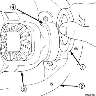
NOTE: It is difficult to salvage the differential side bearings during the removal procedure. Install replacement bearings if necessary.
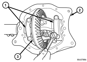
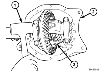
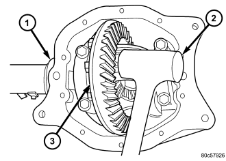
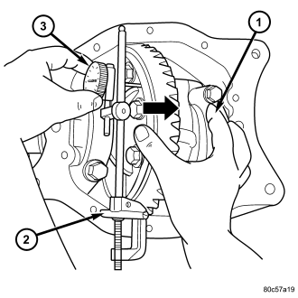
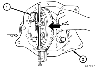
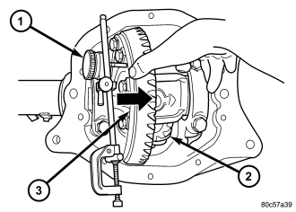
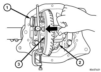
CAUTION: Never spread the differential housing over 0.34 mm (0.013 in.). Failure to follow these procedure could distorted or damaged the housing.
GEAR BACKLASH
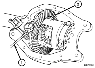
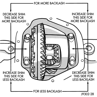
After the proper backlash is achieved, perform Gear Contact Pattern Analysis procedure.
GEAR CONTACT PATTERN
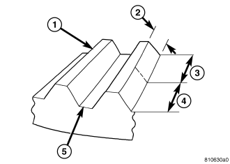
The ring gear and pinion teeth contact patterns will show if the pinion depth is correct in the housing. It will also show if the ring gear backlash has been adjusted correctly. The backlash can be adjusted within specifications to achieve desired tooth contact patterns.
The TOP LAND (1) of the gear tooth is the top surface of the tooth. The PROFILE (2) of the gear tooth is the depth of the tooth. The TOE (3) of the gear is the portion of the tooth surface at the end towards the center. The HEEL (4) of the gear is the portion of the tooth at the outer-end. The ROOT (5) of the gear tooth is the lowest portion of the tooth.
NOTE: If the PROFILE across the tooth is the same it is a 3 Axis cut gear. If the PROFILE across the tooth is tapered it is a 2 Axis cut gear.
The areas on the ring gear teeth with the greatest degree of contact against the pinion teeth will squeegee the compound to the areas with the least amount of contact. Note and compare patterns on the ring gear teeth to Gear Tooth Contact Patterns chart and adjust pinion depth and gear backlash as necessary.
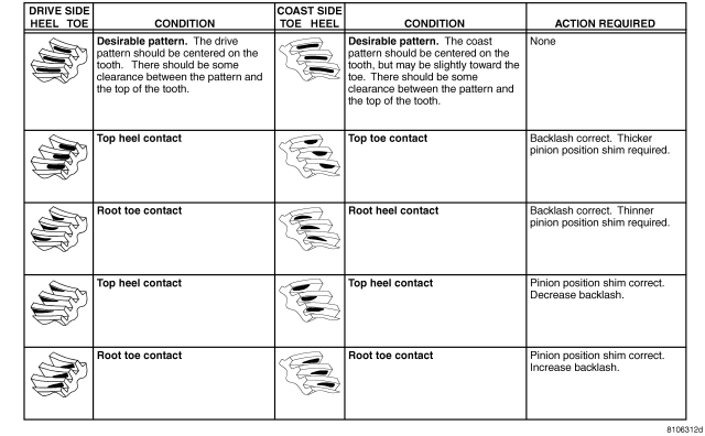
DIFFERENTIAL BEARING PRELOAD CHECK
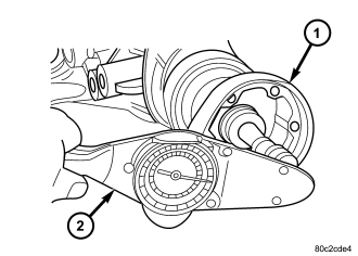
The final check on the differential assembly before installing the axles, is pinion torque to rotate (1) and differential combined with an inch pound torque wrench (2). This will verify the correct differential bearing preload.
Total Torque to Rotate (TTR) is pinion torque to rotate plus:
- Gear Ratio 3.55 - 0.48-0.78 N·m (4.2-6.9 in. lbs.)
- Gear Ratio 3.73 - 0.45-0.75 N·m (3.9-6.6 in. lbs.)
If TTR is high, decrease shim thickness equally on both sides of the differential and check TTR again. If TTR is low, increase shim thickness equally on both sides of the differential and check TTR again.