C2100–BATTERY VOLTAGE LOW
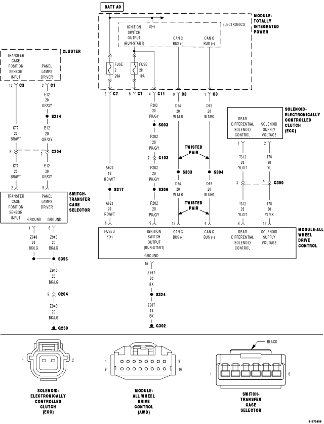
For a complete wiring diagram Refer to Section 8W
- When Monitored:
Continuously.
- Set Condition:
The All Wheel Drive Control Module detects that system voltage is below 8.0 volts for 10 seconds.
| Possible Causes |
| CHARGING SYSTEM DTCS PRESENT |
| (F202) IGNITION SWITCH OUTPUT (RUN/START) CIRCUIT OPEN OR HIGH RESISTANCE |
| (A923) FUSED B(+) CIRCUIT OPEN OR HIGH RESISTANCE |
| (Z967) GROUND CIRCUIT OPEN OR HIGH RESISTANCE |
| ALL WHEEL DRIVE (AWD) CONTROL MODULE |
| TOTALLY INTEGRATED POWER MODULE (TIPM) |
Diagnostic Test
1.CHARGING SYSTEM DTCS PRESENTAre there any Charging System or related voltage DTCs present?
Yes
- Refer to the symptom list and perform any Charging System DTC diagnostic procedures before continuing with this test.
No
- Go to 2
2.CHECK FOR ACTIVE DTC
Is the DTC active at this time?
Yes
- Go to 3
No
- Go to 10
3.CHECK THE TIPM FUSED B(+) VOLTAGE
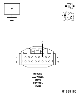
Is the voltage above 8 volts?
Yes
- Go to 4
No
- Go to 9
4.CHECK THE TIPM IGNITION SWITCH OUTPUT RUN/START VOLTAGE
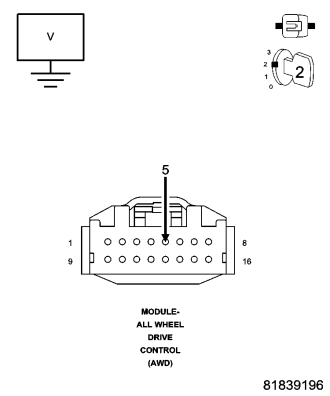
Is the voltage above 8 volts?
Yes
- Go to 5
No
- Go to 9
5.(A923) FUSED B(+) CIRCUIT OPEN OR HIGH RESISTANCE
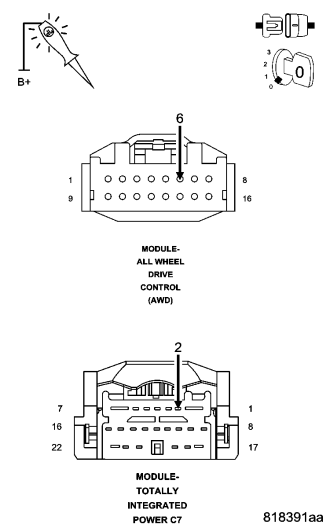
NOTE: The test light must illuminate brightly. Compare the brightness to that of a direct connection to the battery.
Does the test light illuminate brightly?
Yes
- Go to 6
No
- Repair the (F202) Ignition Switch Output (RUN/START) circuit for an open circuit or high resistance.
- Perform AWD Control Module VERIFICATION TEST. (Refer to 3 - DIFFERENTIAL & DRIVELINE/ELECTRONICALLY CONTROLLED CLUTCH - STANDARD PROCEDURE).
6.(F202) IGNITION SWITCH OUTPUT (RUN/START) CIRCUIT OPEN OR HIGH RESISTANCE
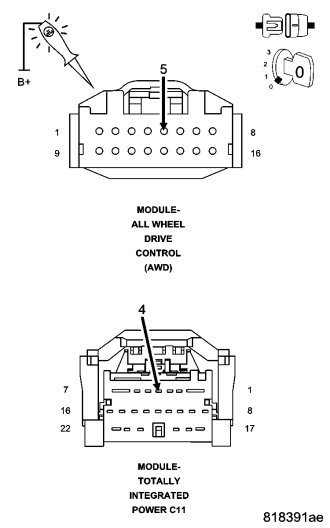
NOTE: The test light must illuminate brightly. Compare the brightness to that of a direct connection to the battery.
Does the test light illuminate brightly?
Yes
- Go to 7
No
- Repair the (F202) Ignition Switch Output (RUN/START) circuit for an open circuit or high resistance.
- Perform AWD Control Module VERIFICATION TEST. (Refer to 3 - DIFFERENTIAL & DRIVELINE/ELECTRONICALLY CONTROLLED CLUTCH - STANDARD PROCEDURE).
7.(Z967) GROUND CIRCUIT OPEN OR HIGH RESISTANCE
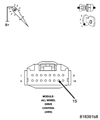
NOTE: The test light must illuminate brightly. Compare the brightness to that of a direct connection to the battery.
Does the test light illuminate brightly?
Yes
- Go to 8
No
- Repair the (Z967) Ground circuit for an open circuit or high resistance.
- Perform AWD Control Module VERIFICATION TEST. (Refer to 3 - DIFFERENTIAL & DRIVELINE/ELECTRONICALLY CONTROLLED CLUTCH - STANDARD PROCEDURE).
8.AWD CONTROL MODULE
NOTE: Before continuing, check the AWD Module harness connector terminals for corrosion, damage, or terminal push out. Repair as necessary.
Were any problems found?
Repair
- Replace the AWD Control Module in accordance with the Service information.
- Perform AWD Control Module VERIFICATION TEST. (Refer to 3 - DIFFERENTIAL & DRIVELINE/ELECTRONICALLY CONTROLLED CLUTCH - STANDARD PROCEDURE).
9.TOTALLY INTEGRATED POWER MODULE
NOTE: Before continuing, check the TIPM harness connector terminals for corrosion, damage, or terminal push out. Repair as necessary.
Were any problems found?
Repair
- Replace the Totally Integrated Power Module in accordance with the Service Information.
- Perform AWD Control Module VERIFICATION TEST. (Refer to 3 - DIFFERENTIAL & DRIVELINE/ELECTRONICALLY CONTROLLED CLUTCH - STANDARD PROCEDURE).
10.INTERMITTENT WIRING AND CONNECTORS
Were there any problems found?
Yes
- Repair as necessary.
- Perform AWD Control Module VERIFICATION TEST. (Refer to 3 - DIFFERENTIAL & DRIVELINE/ELECTRONICALLY CONTROLLED CLUTCH - STANDARD PROCEDURE)
No
- Test Complete.