B210D–BATTERY VOLTAGE LOW – DDM – PDM
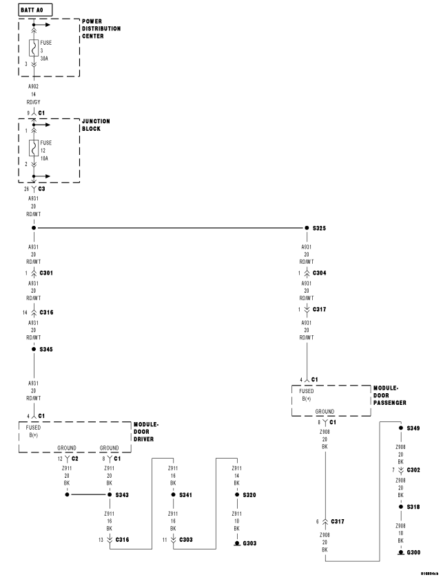
For a complete wiring diagram Refer to Section 8W.
- When Monitored:
Continuously
- Set Condition:
If the Driver/Passenger Door Module senses voltage is less than 8.5 volts on the (A931) Fused B(+) circuit.
| POSSIBLE CAUSES |
| FOR THE DRIVER MEMORY MIRROR SYSTEM: |
| BATTERY / CHARGING SYSTEM |
| (A931) FUSED B(+) CIRCUIT SHORTED |
| (A931) FUSED B(+) CIRCUIT OPEN |
| (Z911) GROUND CIRCUIT(S) OPEN |
| DRIVER DOOR MODULE |
| FOR THE PASSENGER MEMORY MIRROR SYSTEM: |
| BATTERY / CHARGING SYSTEM |
| (A931) FUSED B(+) CIRCUIT SHORTED |
| (A931) FUSED B(+) CIRCUIT OPEN |
| (Z908) GROUND CIRCUIT OPEN |
| PASSENGER DOOR MODULE |
NOTE: Since this DTC can set in the Driver Door Module (DDM) and in the Passenger Door Module (PDM) this procedure addresses both systems' circuits and components. Select only that which applies to the system you are diagnosing.
Diagnostic Test
1.CHECK FOR ENGINE DTCsDoes the scan tool display any BATTERY VOLTAGE LOW related DTCs?
Yes
- Diagnose and repair the DTC(s). (Refer to 9 - ENGINE - DIAGNOSIS AND TESTING) for the diagnostic test procedure(s).
No
- Go To 2
2.VERIFY THAT THE DRIVER DOOR MODULE (DDM) OR PASSENGER DOOR MODULE (PDM) IS ACTIVE ON THE BUS
NOTE: Ensure that the IOD fuse is installed and that battery voltage is between 10.0 and 16.0 volts.
NOTE: A red X will display next to the module that is not communicating, indicating that the module is not active on the Bus network. A green check indicates that the module is active on the Bus network.
Does the scan tool display a red X next to the Driver or Passenger Door Module (DDM or PDM)?
Yes
- (Refer to 8 - ELECTRICAL/ELECTRONIC CONTROL MODULES - DIAGNOSIS AND TESTING) for No Response diagnostic test procedures.
No
- Go To 3
3.TEST FOR INTERMITTENT CONDITION
Does the scan tool display: B210D BATTERY VOLTAGE LOW?
Yes
- Go To 4
No
- The conditions that caused this code to set are not present at this time. Using the wiring diagram/schematic as a guide, inspect the wiring and connectors.
- Perform BODY VERIFICATION TEST – VER 1. (Refer to 8 - ELECTRICAL/ELECTRONIC CONTROL MODULES - STANDARD PROCEDURE).
4.CHECK FOR POWER ON THE (A931) FUSED B(+) CIRCUIT AT THE DRIVER OR PASSENGER DOOR MODULE
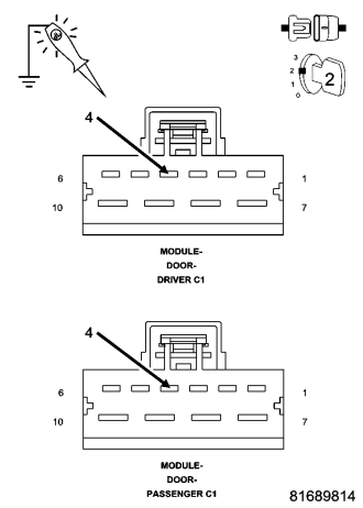
For the Driver Memory Mirror System, proceed as follows:
- Turn the ignition off.
- Disconnect the Driver Door Module C1 connector.
- Turn the ignition on.
- Using a 12-volt test light connected to ground, check the (A931) Fused B(+) circuit.
For the Passenger Memory Mirror System, proceed as follows:
- Turn the ignition off.
- Disconnect the Passenger Door Module C1 connector.
- Turn the ignition on.
- Using a 12-volt test light connected to ground, check the (A931) Fused B(+) circuit.
Does the test light illuminate brightly?
Yes
- Go To 5
No
- Repair the (A931) Fused B(+) circuit for an open or short.
- Perform BODY VERIFICATION TEST – VER 1. (Refer to 8 - ELECTRICAL/ELECTRONIC CONTROL MODULES - STANDARD PROCEDURE).
5.CHECK THE (Z911) OR THE (Z908) GROUND CIRCUITS FOR AN OPEN
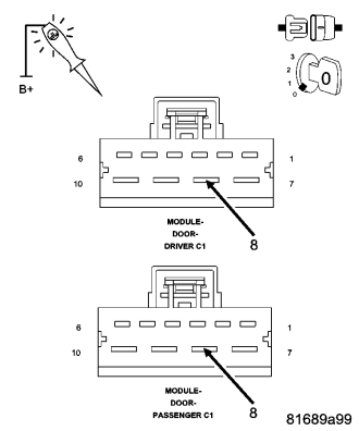
For the Driver Memory Mirror System, proceed as follows:
- Using a 12-volt test light connected to 12-volts, check the (Z911) ground circuit in the Driver Door Module C1 connector.
For the Passenger Memory Mirror System, proceed as follows:
- Using a 12-volt test light connected to 12-volts, check the (Z908) ground circuit in the Passenger Door Module C1 connector.
Does the test light illuminate brightly?
Yes, Driver Mirror
- Replace the Driver Door Module in accordance with the Service Information.
- Perform BODY VERIFICATION TEST – VER 1. (Refer to 8 - ELECTRICAL/ELECTRONIC CONTROL MODULES - STANDARD PROCEDURE).
Yes, Passenger Mirror
- Replace the Passenger Door Module in accordance with the Service Information.
- Perform BODY VERIFICATION TEST – VER 1. (Refer to 8 - ELECTRICAL/ELECTRONIC CONTROL MODULES - STANDARD PROCEDURE).
No, Driver Mirror
- Repair the (Z911) ground circuit(s) for an open.
- Perform BODY VERIFICATION TEST – VER 1. (Refer to 8 - ELECTRICAL/ELECTRONIC CONTROL MODULES - STANDARD PROCEDURE).
No, Passenger Mirror
- Repair the (Z908) ground circuit for an open.
- Perform BODY VERIFICATION TEST – VER 1. (Refer to 8 - ELECTRICAL/ELECTRONIC CONTROL MODULES - STANDARD PROCEDURE).