STANDARD PROCEDURE - CONNECTING ROD BEARING FITTING
Inspect the connecting rod bearings for scoring. Check the bearings for normal wear patterns, scoring, grooving, fatigue and pitting. Replace any bearing that shows abnormal wear.
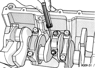
Inspect the connecting rod journals for signs of scoring, nicks and burrs.
Misaligned or bent connecting rods can cause abnormal wear on pistons, piston rings, cylinder walls, connecting rod bearings and crankshaft connecting rod journals. If wear patterns or damage to any of these components indicate the probability of a misaligned connecting rod, inspect it for correct rod alignment. Replace misaligned, bent or twisted connecting rods.
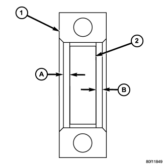
Center bearing insert (2) in connecting rod.
Center bearing insert (2) in connecting rod (1).
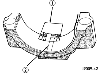
Plastigage should indicate the same clearance across the entire width of the insert. If the clearance varies, it may be caused by either a tapered journal, bent connecting rod or foreign material trapped between the insert and cap or rod.
| Bearing Mark | SIZE | USED WITH |
| JOURNAL SIZE | ||
| .025 US | .025 mm | 50.983-50.967 mm |
| (.001 in.) | (2.0073-2.0066 in.) | |
| Std. | STANDARD | 50.992-51.008 mm |
| (2.0076-2.0082 in.) | ||
| .250 US | .250 mm | 50.758-50.742 mm |
| (.010 in.) | (1.9984-1.9978 in.) |
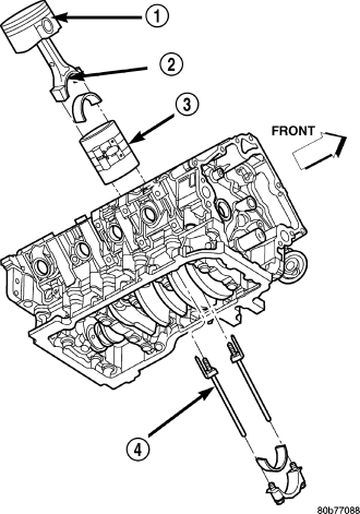
CAUTION: Connecting Rod Bolts are Torque to Yield Bolts and Must Not Be Reused. Always replace the Rod Bolts whenever they are loosened or removed.
Slide snug-fitting feeler gauge between the connecting rod and crankshaft journal flange. Refer to Engine Specifications for the proper clearance. Replace the connecting rod if the side clearance is not within specification.