85–BLOWER NOT ON HIGH DURING COOLDOWN TEST (MTC)
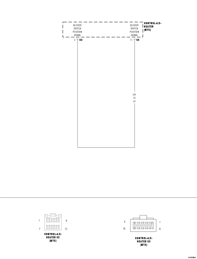
For a complete wiring diagram Refer to Section 8W.
- When Monitored:
When executing the Cooldown Test.
- Set Condition:
If the A/C Heater Control sensed that the blower was not operating at high speed while the Cooldown Test was running.
| Possible Causes |
| BLOWER CONTROL DID NOT REMAIN ON THE HIGH SPEED SETTING FOR THE ENTIRE COOLDOWN TEST |
| BLOWER MOTOR / RELATED CIRCUITS |
| (C41) BLOWER SWITCH POSITION SIGNAL CIRCUIT SHORTED TO (C121) SENSOR GROUND CIRCUIT |
| (C41) BLOWER SWITCH POSITION SIGNAL CIRCUIT SHORTED TO GROUND |
| (C41) BLOWER SWITCH POSITION SIGNAL CIRCUIT OPEN |
| A/C HEATER CONTROL |
NOTE: This DTC will display as active if the ignition is not cycled after running the Cooldown Test. Otherwise, it will display as stored until cleared.
Diagnostic Test
1.CHECK THE BLOWER SPEED SETTINGWas the blower control set to high speed for the entire Cooldown Test?
Yes
- Go To 2
No
- Start the engine, set the blower control to high speed, and then run the Cooldown Test again.
- Perform BODY VERIFICATION TEST - VER 1. (Refer to 8 - ELECTRICAL/ELECTRONIC CONTROL MODULES - STANDARD PROCEDURE).
2.CHECK THE (C41) BLOWER SWITCH POSITION SIGNAL CIRCUIT FOR A SHORT TO THE (C121) SENSOR GROUND CIRCUIT
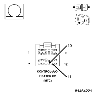
Is the resistance below 10K ohms?
Yes
- Repair the (C41) Blower Switch Position Signal circuit for a short to the (C121) Sensor Ground circuit. Run the Cooldown Test again after the repair is complete.
- Perform BODY VERIFICATION TEST - VER 1. (Refer to 8 - ELECTRICAL/ELECTRONIC CONTROL MODULES - STANDARD PROCEDURE).
No
- Go To 3
3.CHECK THE (C41) BLOWER SWITCH POSITION SIGNAL CIRCUIT VOLTAGE
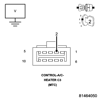
Is the voltage above 4.8 volts?
Yes
- Check the blower motor and related circuits for the cause of blower operation problems and repair as necessary. Run the Cooldown Test again after the repair is complete.
- Perform BODY VERIFICATION TEST - VER 1. (Refer to 8 - ELECTRICAL/ELECTRONIC CONTROL MODULES - STANDARD PROCEDURE).
No
- Go To 4
4.CHECK THE (C41) BLOWER SWITCH POSITION SIGNAL CIRCUIT FOR A SHORT TO GROUND
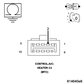
Is the resistance below 10K ohms?
Yes
- Repair the (C41) Blower Switch Position Signal circuit for a short to ground. Run the Cooldown Test again after the repair is complete.
- Perform BODY VERIFICATION TEST - VER 1. (Refer to 8 - ELECTRICAL/ELECTRONIC CONTROL MODULES - STANDARD PROCEDURE).
No
- Go To 5
5.CHECK (C41) BLOWER SWITCH POSITION SIGNAL CIRCUIT FOR AN OPEN
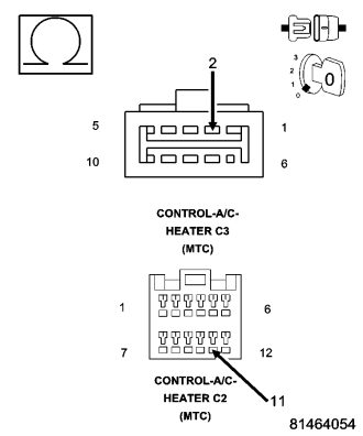
Is the resistance below 5.0 ohms?
Yes
- Replace the A/C Heater Control in accordance with the Service Information. Run the Cooldown Test again after the repair is complete.
- Perform BODY VERIFICATION TEST - VER 1. (Refer to 8 - ELECTRICAL/ELECTRONIC CONTROL MODULES - STANDARD PROCEDURE).
No
- Repair the (C41) Blower Switch Position Signal circuit for an open. Run the Cooldown Test again after the repair is complete.
- Perform BODY VERIFICATION TEST - VER 1. (Refer to 8 - ELECTRICAL/ELECTRONIC CONTROL MODULES - STANDARD PROCEDURE).