B1605–RIGHT SOLAR SENSOR CIRCUIT HIGH (ATC)
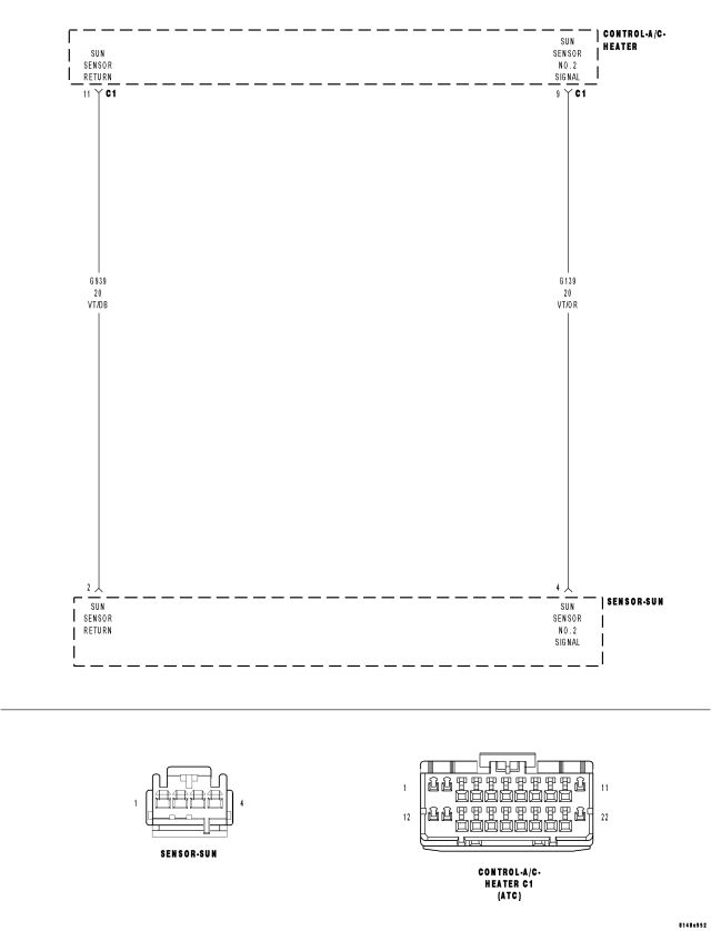
For a complete wiring diagram Refer to Section 8W.
- When Monitored:
With ignition on.
- Set Condition:
If the Right Sunload Sensor input is out of range toward the high voltage threshold.
| Possible Causes |
| (G139) SUN SENSOR NO. 2 SIGNAL CIRCUIT SHORTED TO VOLTAGE |
| (G139) SUN SENSOR NO. 2 SIGNAL CIRCUIT OPEN |
| (G939) SUN SENSOR RETURN CIRCUIT OPEN |
| SUN SENSOR |
| A/C HEATER CONTROL |
NOTE: This DTC must be active for the results of this test to be valid. Do not perform this test if this DTC is stored. Refer to HVAC System Test (ATC) for stored DTC test procedures.
Diagnostic Test
1.CHECK (G139) SUN SENSOR NO. 2 SIGNAL CIRCUIT VOLTAGE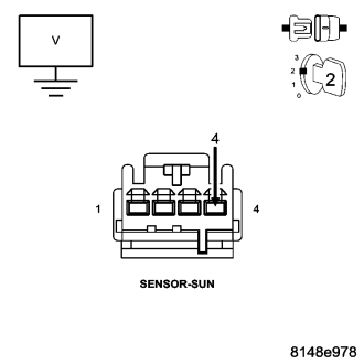
What voltage is present?
Above 5.2 Volts
- Go To 2
4.8 Volts to 5.2 Volts
- Go To 3
Below 4.8 Volts
- Go To 5
2.CHECK (G139) SUN SENSOR NO. 2 SIGNAL CIRCUIT FOR A SHORT TO VOLTAGE
Is the voltage above 0.2 volts?
Yes
- Repair the (G139) Sun Sensor No. 2 Signal circuit for a short to voltage.
- Perform BODY VERIFICATION TEST – VER 1. (Refer to 8 - ELECTRICAL/ELECTRONIC CONTROL MODULES - STANDARD PROCEDURE).
No
- Replace the A/C Heater Control in accordance with the Service Information.
- Perform BODY VERIFICATION TEST – VER 1. (Refer to 8 - ELECTRICAL/ELECTRONIC CONTROL MODULES - STANDARD PROCEDURE).
3.CHECK (G939) SUN SENSOR RETURN CIRCUIT FUNCTION
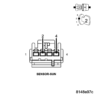
Is the voltage below 0.2 volts?
Yes
- Replace the Sun Sensor in accordance with the Service Information.
- Perform BODY VERIFICATION TEST – VER 1. (Refer to 8 - ELECTRICAL/ELECTRONIC CONTROL MODULES - STANDARD PROCEDURE).
No
- Go To 4
4.CHECK (G939) SUN SENSOR RETURN CIRCUIT FOR AN OPEN
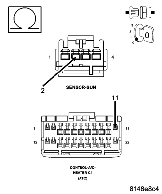
Is the resistance below 5.0 ohms?
Yes
- Replace the A/C Heater Control in accordance with the Service Information.
- Perform BODY VERIFICATION TEST – VER 1. (Refer to 8 - ELECTRICAL/ELECTRONIC CONTROL MODULES - STANDARD PROCEDURE).
No
- Repair the (G939) Sun Sensor Return circuit for an open.
- Perform BODY VERIFICATION TEST – VER 1. (Refer to 8 - ELECTRICAL/ELECTRONIC CONTROL MODULES - STANDARD PROCEDURE).
5.CHECK (G139) SUN SENSOR NO. 2 SIGNAL CIRCUIT FOR AN OPEN
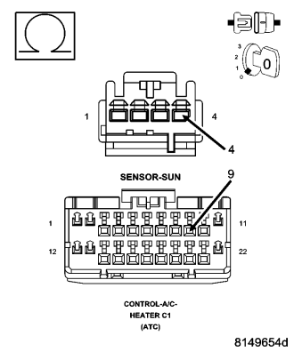
Is the resistance below 5.0 ohms?
Yes
- Replace the A/C Heater Control in accordance with the Service Information.
- Perform BODY VERIFICATION TEST – VER 1. (Refer to 8 - ELECTRICAL/ELECTRONIC CONTROL MODULES - STANDARD PROCEDURE).
No
- Repair the (G139) Sun Sensor No. 2 Signal circuit for an open.
- Perform BODY VERIFICATION TEST – VER 1. (Refer to 8 - ELECTRICAL/ELECTRONIC CONTROL MODULES - STANDARD PROCEDURE).