C107C-BRAKE PEDAL SWITCH 1/2 STUCK
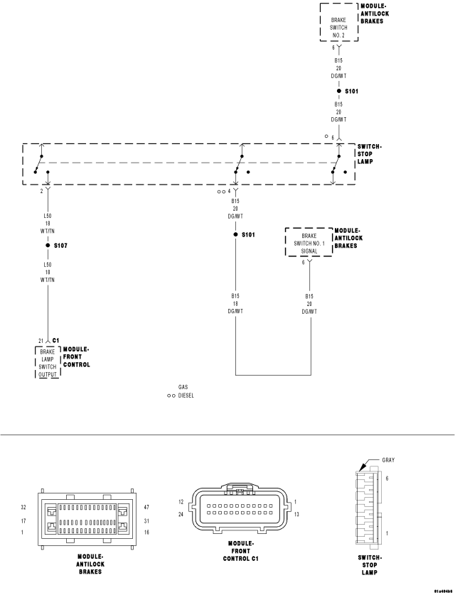
For a complete wiring diagram Refer to Section 8W.
- When Monitored:
With the ignition on, but not during first run.
- Set Condition:
When the Anti-Lock Brake Module detects a mismatch between the two signals of the redundant stop lamp switch.
| Possible Causes |
| TERMINAL/CONNECTOR/WIRING HARNESS DAMAGE |
| STOP LAMP SWITCH |
| (B15) BRAKE SWITCH NO. 1 SIGNAL CIRCUIT OPEN |
| (L50) BRAKE LAMP SWITCH OUTPUT CIRCUIT OPEN |
| FRONT CONTROL MODULE |
| ANTI-LOCK BRAKE MODULE |
Diagnostic Test
1.CHECK FOR A DTC C107C-BRAKE PEDAL SWITCH 1/2 STUCKNOTE: This DTC must be active for the results of this test to be valid.
Does the scan tool display: C107C-BRAKE PEDAL SWITCH 1/2 STUCK?
Yes
- Go To 2
No
- Refer to the INTERMITTENT CONDITION diagnostic procedure.
- The condition that caused the symptom is currently not present. Inspect the related wiring for a possible intermittent condition. Look for any chafed, pierced, pinched, or partially broken wires.
- Refer to the ABS-INTERMITTENT CONDITION TEST. (Refer to 5 - BRAKES - DIAGNOSIS AND TESTING).
2.CHECK THE TERMINALS/CONNECTORS/WIRING HARNESS FOR DAMAGE
Were any problems found?
Yes
- Repair as necessary.
- Perform ABS VERIFICATION TEST. (Refer to 5 - BRAKES - STANDARD PROCEDURE).
No
- Go To 3
3.CHECK THE (L50) BRAKE LAMP SWITCH OUTPUT CIRCUIT WHILE DEPRESSING AND RELEASING BRAKE PEDAL
Does the brake lights illumination with brake applied?
Yes
- Go To 4
No
- Repair open (L50) Brake Lamp Switch Output circuit or open FCM.
- Perform ABS VERIFICATION TEST. (Refer to 5 - BRAKES - STANDARD PROCEDURE).
4.CHECK THE (B15) BRAKE SWITCH NO. 1 SIGNAL CIRCUIT WHILE DEPRESSING AND RELEASING BRAKE PEDAL
Does the Brake Switch status change when brakes are applied?
Yes
- Replace the Anti-lock Bake Module in accordance with the Service Information.
- Perform ABS VERIFICATION TEST. (Refer to 5 - BRAKES - STANDARD PROCEDURE).
No
- Go To 5
5.CHECK THE (B15) BRAKE SWITCH NO. 1 SIGNAL CIRCUIT FOR AN OPEN
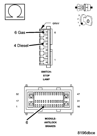
Is the resistance below 5.0 ohms?
Yes
- Replace the Stop Lamp Switch in accordance with the Service Information.
- Perform ABS VERIFICATION TEST. (Refer to 5 - BRAKES - STANDARD PROCEDURE).
No
- Repair the (B15) Brake Switch No. 1 Signal circuit for an open.
- Perform ABS VERIFICATION TEST. (Refer to 5 - BRAKES - STANDARD PROCEDURE).