P2111-ELECTRONIC THROTTLE CONTROL - UNABLE TO CLOSE
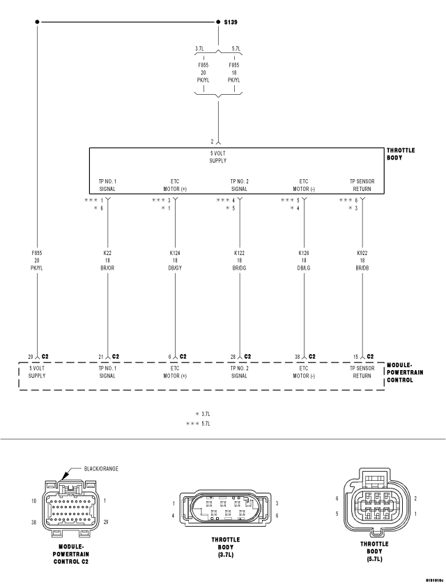
For a complete wiring diagram Refer to Section 8W.
- When Monitored:
Ignition on and battery voltage greater than 10 volts.
- Set Condition:
Just after key on, the throttle is opened and closed to test the system. If the TP Sensor does not return to Limp Home Position at the end of this test, this DTC will set. One trip fault and the code will set within 5 seconds. ETC light is flashing.
| Possible Causes |
| THROTTLE PLATE STUCK ABOVE LIMP HOME POSITION |
| TP SENSOR NO.1 AND TP SENSOR NO.2 BOTH READ 2.5 VOLTS |
| (K124) ETC POSITIVE CIRCUIT SHORTED TO BATTERY VOLTAGE |
| (K124) ETC POSITIVE CIRCUIT OPEN |
| (K126) ETC NEGATIVE CIRCUIT OPEN |
| (K124) ETC POSITIVE CIRCUIT SHORTED TO GROUND |
| (K126) ETC NEGATIVE CIRCUIT SHORTED TO GROUND |
| PCM |
Always perform the Pre-Diagnostic Troubleshooting procedure before proceeding. (Refer to 9 - ENGINE - DIAGNOSIS AND TESTING).
Diagnostic Test
1.ACTIVE DTCNOTE: Maximum engine speed could be reduced while this fault is active, it just depends where the throttle gets stuck.
NOTE: The PCM tests the ETC Motor by opening and closing the Throttle Plate before starting the engine. If during this test the Throttle plate does not return to the closed position this DTC sets.
NOTE: Diagnose any TP Sensor or 5-Volt Supply DTCs before continuing.
Is the DTC Active at this time?
Yes
- Go To 2
No
- Refer to the INTERMITTENT CONDITION Diagnostic Procedure.
- Perform the POWERTRAIN VERIFICATION TEST. (Refer to 9 - ENGINE - STANDARD PROCEDURE)
2.THROTTLE PLATE STUCK OPEN
NOTE: The PCM tests the ETC Motor by opening and closing the Throttle Plate before starting the engine. If during this test the Throttle plate does not return to the closed position this DTC sets.
Does the Throttle Plate move?
Yes
- Go To 3
No
- Remove the debris if possible or replace the Throttle Body Assembly if signs of physical damage are present. Disconnect the Battery when replacing the Throttle Body Assembly. After installation is complete, use a scan tool and perform the ETC RELEARN function.
- Perform the POWERTRAIN VERIFICATION TEST. (Refer to 9 - ENGINE - STANDARD PROCEDURE)
3.TP SENSOR NO.1 AND TP SENSOR NO.2 BOTH EQUAL 2.5 VOLTS
Are both TP Sensor readings stuck at 2.5 volts?
Yes
- Check the TP Sensor Signal circuits for excessive resistance, being shorted to each other, or shorted to the Sensor Return circuit.
- Perform the POWERTRAIN VERIFICATION TEST. (Refer to 9 - ENGINE - STANDARD PROCEDURE)
No
- Go To 4
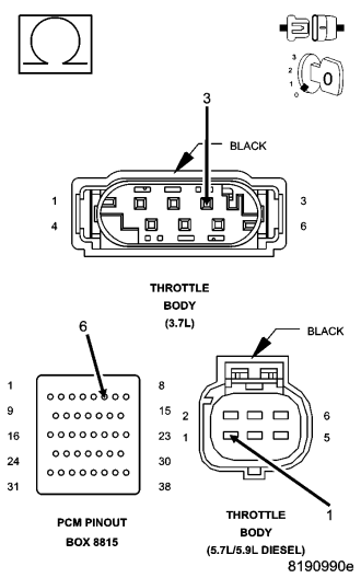
4.(K124) ETC POSITIVE CIRCUIT SHORTED TO BATTERY VOLTAGE
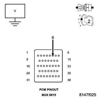
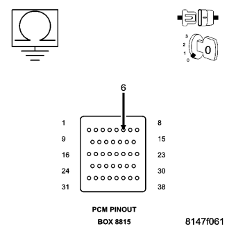
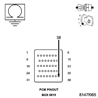
CAUTION: Do not probe the PCM harness connectors. Probing the PCM harness connectors will damage the PCM terminals resulting in poor terminal to pin connection. Install Miller Special Tool #8815 to perform the diagnostics.
Does the test light illuminate brightly?
Yes
- Repair the short to battery voltage on the (K124) ETC Positive circuit.
- Perform the POWERTRAIN VERIFICATION TEST. (Refer to 9 - ENGINE - STANDARD PROCEDURE)
No
- Go To 5
5.(K124) ETC POSITIVE CIRCUIT OPEN
Is the resistance below 5.0 ohms?
Yes
- Go To 6
No
- Repair the open in the (K124) ETC Positive circuit.
- Perform the POWERTRAIN VERIFICATION TEST. (Refer to 9 - ENGINE - STANDARD PROCEDURE)
6.(K126) ETC NEGATIVE CIRCUIT OPEN
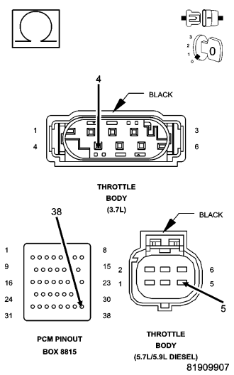
Is the resistance below 5.0 ohms?
Yes
- Go To 7
No
- Repair the open in the (K126) ETC Negative circuit.
- Perform the POWERTRAIN VERIFICATION TEST. (Refer to 9 - ENGINE - STANDARD PROCEDURE)
7.(K124) ETC POSITIVE CIRCUIT SHORTED TO GROUND
Is the resistance below 100 ohms?
Yes
- Repair the short to ground in the (K124) ETC Positive circuit.
- Perform the POWERTRAIN VERIFICATION TEST. (Refer to 9 - ENGINE - STANDARD PROCEDURE)
No
- Go To 8
8.(K126) ETC NEGATIVE CIRCUIT SHORTED TO GROUND
Is the resistance below 100 ohms?
Yes
- Repair the short to ground in the (K126) ETC Negative circuit.
- Perform the POWERTRAIN VERIFICATION TEST. (Refer to 9 - ENGINE - STANDARD PROCEDURE)
No
- Go To 9
9.PCM
NOTE: Before continuing, check the PCM harness connector terminals for corrosion, damage, or terminal push out. Repair as necessary.
Were there any problems found?
Yes
- Repair as necessary.
- Perform the POWERTRAIN VERIFICATION TEST. (Refer to 9 - ENGINE - STANDARD PROCEDURE)
No
- Replace and program the Powertrain Control Module per Service Information.
- Perform the POWERTRAIN VERIFICATION TEST. (Refer to 9 - ENGINE - STANDARD PROCEDURE)